
kiwikr.co.nz
|
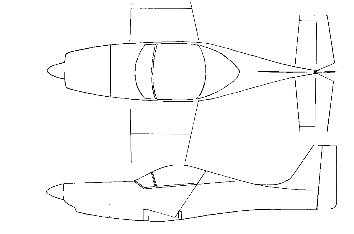
This is my second attempt at building a Horizontal Stabiliser after my building mentor recommended I use the standard KR hinge setup rather than the Dr Dean hinges. I orginally considered just modifying my original HS but after looking at what was required I decided it would just be easier to build a new one from scratch. The new HS will have the following features.
1. The HS will incorporate the NACA63009 profiles sourced from Mark Langfords web site. Please note that I haven't detailed all the steps I have taken in building this second HS if the step has been
detailed previously in the original Horizontal Stabiliser page.
| ||||||
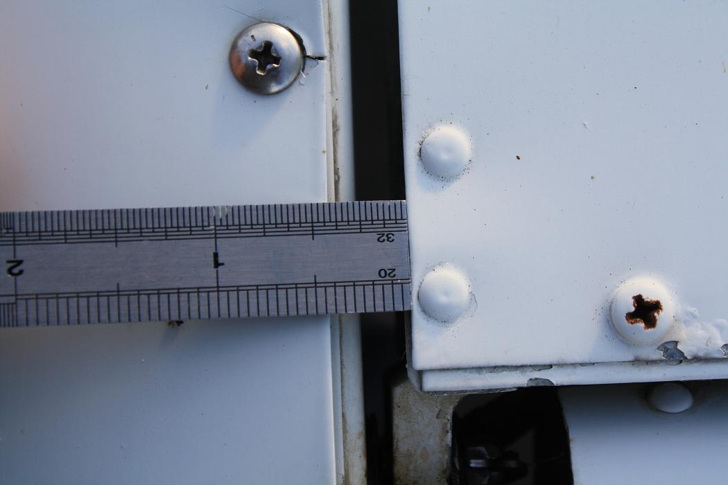 24th Februray 2010. Today I went out to the local airfield to measure the gap between the balance horns of a Cessna 152 so
I could incorporate this spacing into my HS. My building mentor recommended increasing the gap on my HS so I decided to use the
Cessna dimensions as a proven template to work from. The spacing at the side of the balance horn is 1/4".
24th Februray 2010. Today I went out to the local airfield to measure the gap between the balance horns of a Cessna 152 so
I could incorporate this spacing into my HS. My building mentor recommended increasing the gap on my HS so I decided to use the
Cessna dimensions as a proven template to work from. The spacing at the side of the balance horn is 1/4".
| ||||||
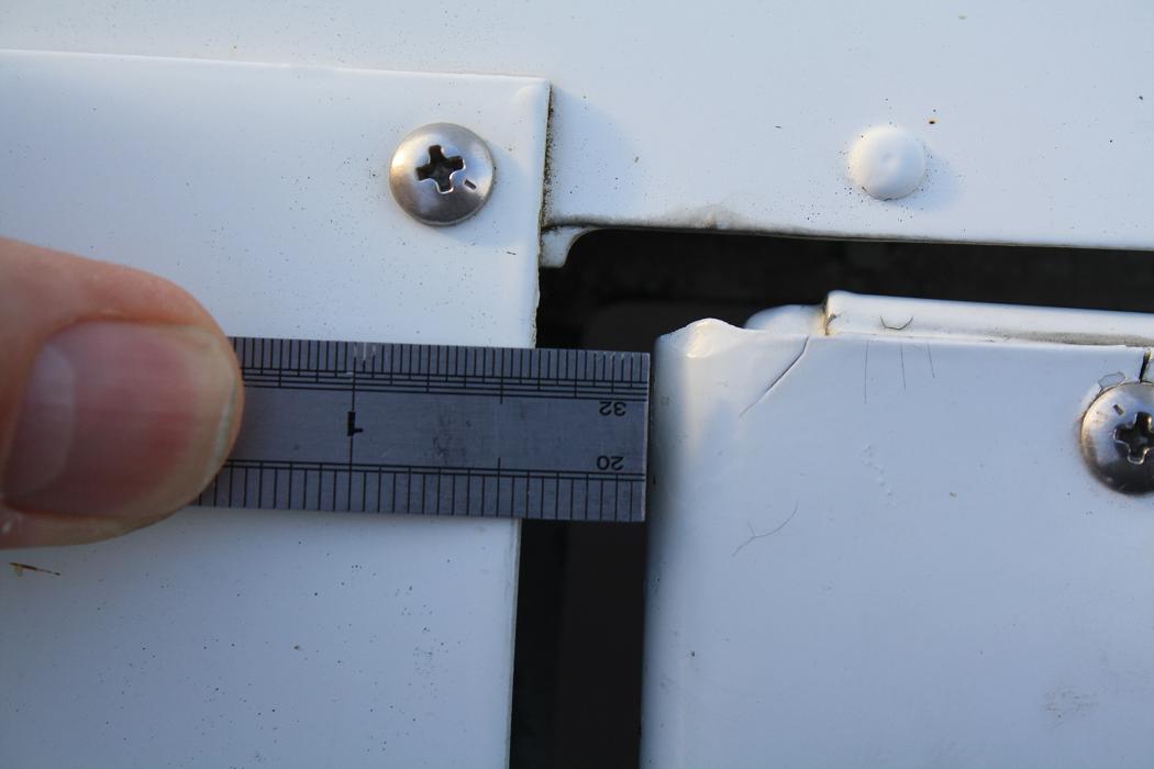 The spacing at the front of the balance horn is 3/8".
| ||||||
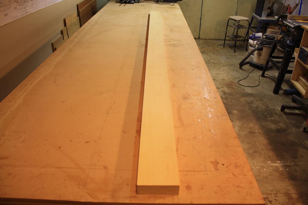 4th March 2010. After a number of attempts at making spars for the new HS without much success, today I went to BBS Timber
in Henderson and purchased a piece of 6" x 2" dressed Yellow Cedar. I had originally purchased rough sawn timber but the
rough surface often hides flaws in the wood which only show up when the timber is dressed. By purchasing the dressed timber
I was able to buy a piece with the straightest grain I could find.
4th March 2010. After a number of attempts at making spars for the new HS without much success, today I went to BBS Timber
in Henderson and purchased a piece of 6" x 2" dressed Yellow Cedar. I had originally purchased rough sawn timber but the
rough surface often hides flaws in the wood which only show up when the timber is dressed. By purchasing the dressed timber
I was able to buy a piece with the straightest grain I could find.
| ||||||
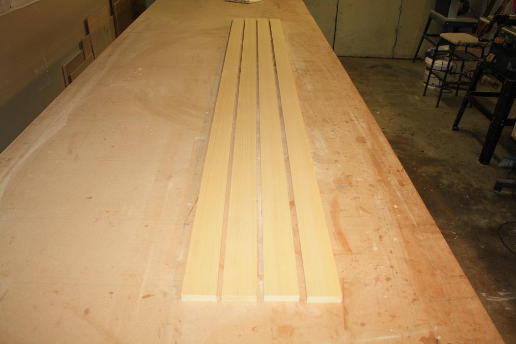 After getting the timber home I cut and dressed it into four spar blanks, (one extra for just in case.)
| ||||||
 7th March 2010. Tonight I spent a couple of hours drawing the dimensions onto the spars. Once again I used Darren Cromptons
dimensions from his web site which can be found here.
I have listed them again below.
7th March 2010. Tonight I spent a couple of hours drawing the dimensions onto the spars. Once again I used Darren Cromptons
dimensions from his web site which can be found here.
I have listed them again below.FORWARD SPAR ------------ Total Length = 90 inches Fwd Face Height At Inner Rib = 59mm less 3.9degrees = 56.8mm Fwd Face Height At Outer Rib = 32mm less 7.8degress = 27.6mm Aft Face Height At Inner Rib = 59mm Aft Face Height At Outer Rib = 32mm CENTRE SPAR ----------- Total Length = 84 inches. Fwd Face Height At Inner Rib = 59.5mm Fwd Face Height At Outer Rib = 42.2mm Aft Face Height At Inner Rib = 59.5mm less 3.0degrees = 57.8mm Aft Face Height At Outer Rib = 42.2mm less 2.9degrees = 40.6mm REAR SPAR --------- Total Length = 90 inches. Fwd Face Height At Inner Rib = 52.8mm Fwd Face Height At Outer Rib = 35.6mm Aft Face Height At Inner Rib = 52.8mm less 5.1degrees = 50.0mm Aft Face Height At Outer Rib = 35.6mm less 4.5degrees = 33.0mm | ||||||
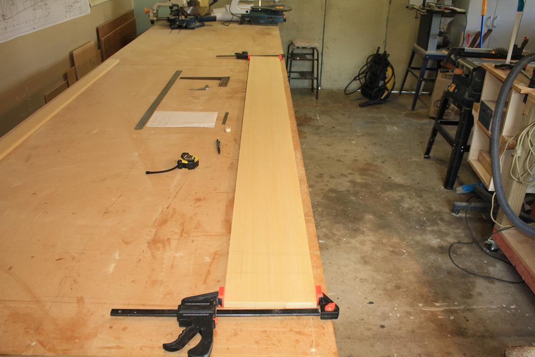
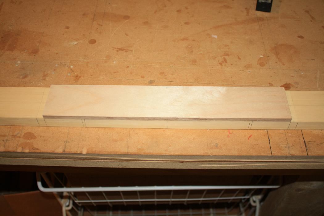
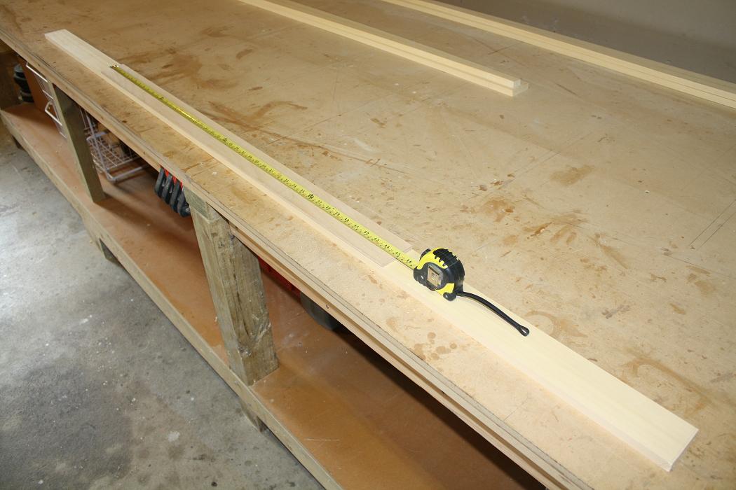 4th April 2010. Today I measured and cut a piece of 6mm ply for the middle spar doubler. While checking the length of this doubler on
the plans I realised that the doubler is exactly half the width of the original middle spar and as such I will need to widen mine to 45"
as I am widening the HS to 7' 6".
4th April 2010. Today I measured and cut a piece of 6mm ply for the middle spar doubler. While checking the length of this doubler on
the plans I realised that the doubler is exactly half the width of the original middle spar and as such I will need to widen mine to 45"
as I am widening the HS to 7' 6".
| ||||||
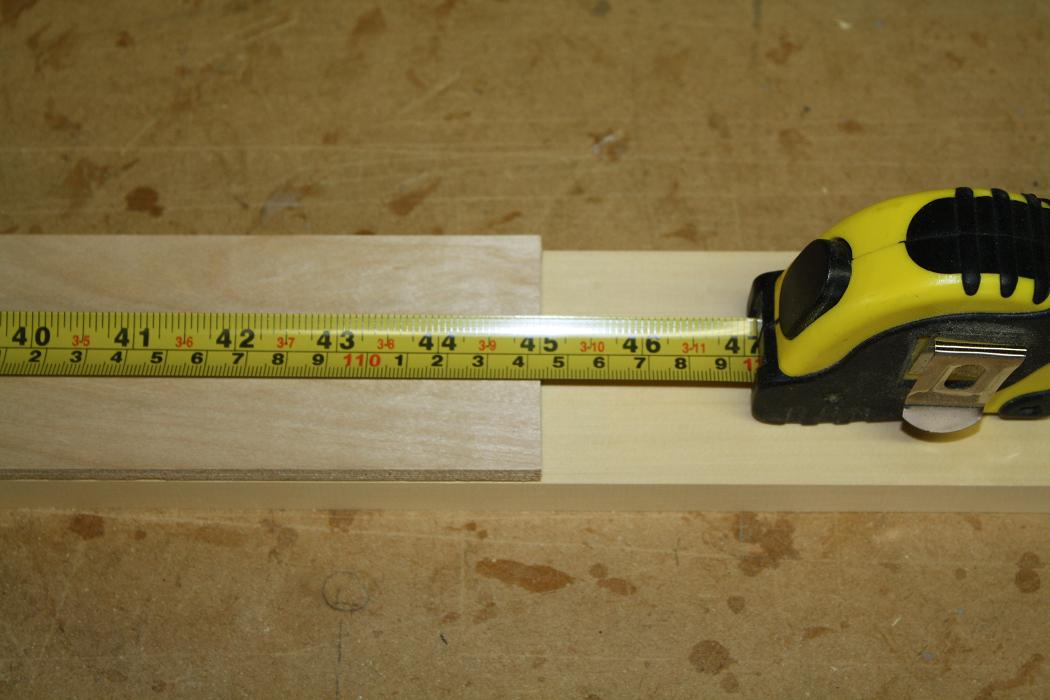 As you can see 45 inches on the button.
| ||||||
 I then setup and glued the doubler into place.
| ||||||
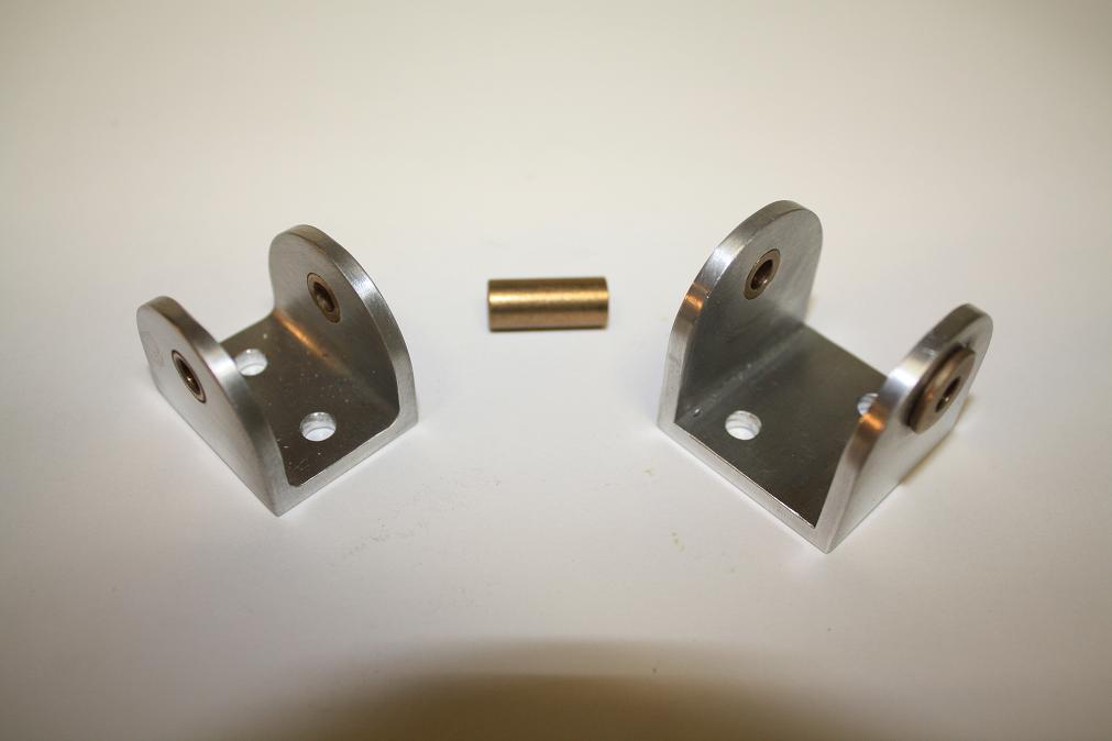
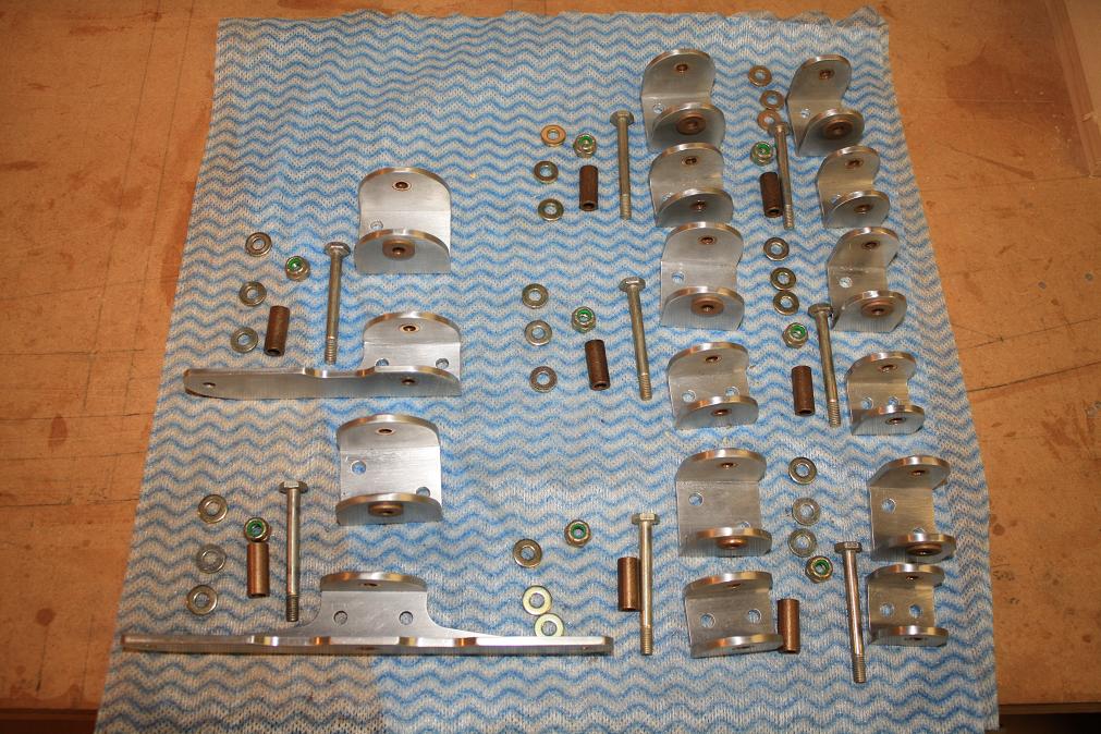
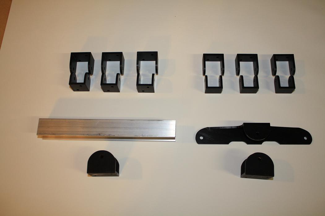 After glueing the doubler into place I then spent some time trying to work out how the KR hinges I have purchased match up into pairs.
This is the complete set of parts as they arrived from the supplier.
After glueing the doubler into place I then spent some time trying to work out how the KR hinges I have purchased match up into pairs.
This is the complete set of parts as they arrived from the supplier.
| ||||||
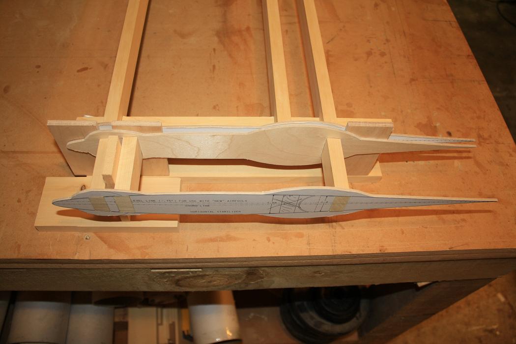
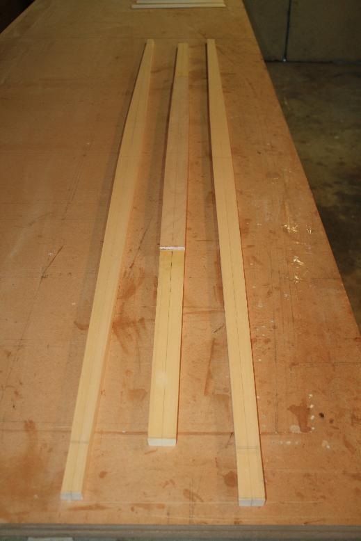 4th - 5th April 2010. I then moved onto shaping the spars to the dimensions required. Here is the result of my efforts.
| ||||||
 6th - 11th April 2010. Cut out the aerofoil templates for the HS.
| ||||||
 I have decided to use the thicker 3/8" template as called out for in the plans at the center rear position. Here you can see the thicker
template. This is made from thicknessed yellow cedar instead of the 2.5mm ply used for the other templates.
I have decided to use the thicker 3/8" template as called out for in the plans at the center rear position. Here you can see the thicker
template. This is made from thicknessed yellow cedar instead of the 2.5mm ply used for the other templates.
| ||||||
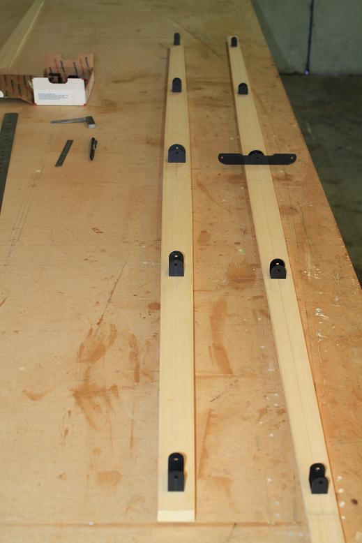 2nd May 2010. Today I laid the hinges out on the center and rear spars to check for alignment. I am not overly happy with the
fit of the hinges as the spars for the NACA63009 profiles are deeper than the standard KR spars. The centre hinge is wide
enough to cover approximately 3/4 of the depth of the spar but the middle and outer hinge pairs cover less that half the depth.
2nd May 2010. Today I laid the hinges out on the center and rear spars to check for alignment. I am not overly happy with the
fit of the hinges as the spars for the NACA63009 profiles are deeper than the standard KR spars. The centre hinge is wide
enough to cover approximately 3/4 of the depth of the spar but the middle and outer hinge pairs cover less that half the depth.
| ||||||
 I have also found that the outer pair of end hinges appear to have a manufacturing fault in that the hinge hole in the
rear hinge channel has been drilled 11/16" from the spar face instead of 5/8". As a result the overall hinge width
between the spars is 1/16" wider than the space available when the spars are mounted in the templates. Also the mounting
holes for all the hinges have only been drilled to take an AN-2 bolt where the plans call out for AN-3 bolts. I have drilled
the holes out to take AN-3 bolts but this does not leave much space for the head of the bolt to fit between the hole
and the inside curve of the aluminium channel. I also managed to stuff up a couple of the hinges when drilling out the holes
so have had to bin them. All in all I have to say I am not overly impressed with the quality of the hinge kit I received
especially given the purchase price.
I have also found that the outer pair of end hinges appear to have a manufacturing fault in that the hinge hole in the
rear hinge channel has been drilled 11/16" from the spar face instead of 5/8". As a result the overall hinge width
between the spars is 1/16" wider than the space available when the spars are mounted in the templates. Also the mounting
holes for all the hinges have only been drilled to take an AN-2 bolt where the plans call out for AN-3 bolts. I have drilled
the holes out to take AN-3 bolts but this does not leave much space for the head of the bolt to fit between the hole
and the inside curve of the aluminium channel. I also managed to stuff up a couple of the hinges when drilling out the holes
so have had to bin them. All in all I have to say I am not overly impressed with the quality of the hinge kit I received
especially given the purchase price.
| ||||||
 The net result of the above is that I have decided to manufacture my own hinges. I will still use the center hinge I purchased
as this is ok and at 1.5" wide is sufficiently wide for the spar. I will however make a new set of hinges which will be 1.25" wide
for the middle set of hinges and also make a set of hinges 1" wide for the outer hinges to replace the ones I stuffed when
trying to drill out the holes. With this plan in mind I ordered some Aluminium channel from a local parts supplier. I asked
for 6061-T6 channel and the supplier sent me 6063-T5 saying this was equivalent to the 6061-T6. Not knowing any better I set
about manufacturing the new hinges. (Note I found out later that 6063-T5 is considerably weaker in Yield Strength than 6061-T6
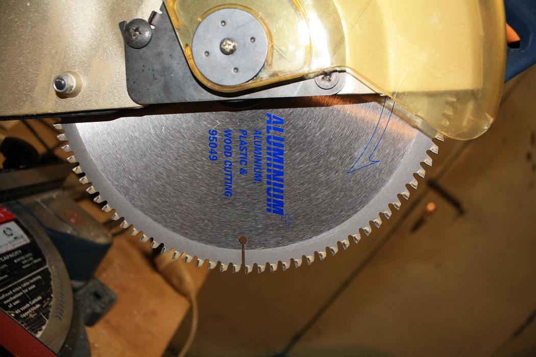
and is not an acceptable replacement.) To manufacturer my own hinges, the first thing I did was purchase an Aluminium cutting
blade for my drop saw.
The net result of the above is that I have decided to manufacture my own hinges. I will still use the center hinge I purchased
as this is ok and at 1.5" wide is sufficiently wide for the spar. I will however make a new set of hinges which will be 1.25" wide
for the middle set of hinges and also make a set of hinges 1" wide for the outer hinges to replace the ones I stuffed when
trying to drill out the holes. With this plan in mind I ordered some Aluminium channel from a local parts supplier. I asked
for 6061-T6 channel and the supplier sent me 6063-T5 saying this was equivalent to the 6061-T6. Not knowing any better I set
about manufacturing the new hinges. (Note I found out later that 6063-T5 is considerably weaker in Yield Strength than 6061-T6
and is not an acceptable replacement.) To manufacturer my own hinges, the first thing I did was purchase an Aluminium cutting
blade for my drop saw.
| ||||||
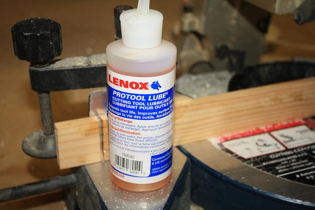 I also purchase some cutting fluid at the same time.
| ||||||
 Apart from the mess, the blade makes it very easy to cut the Aluminium channel stock. I would recommend wearing gloves when
cutting any metal with a blade as the swarf that comes off can be very hot.
Apart from the mess, the blade makes it very easy to cut the Aluminium channel stock. I would recommend wearing gloves when
cutting any metal with a blade as the swarf that comes off can be very hot.
| ||||||
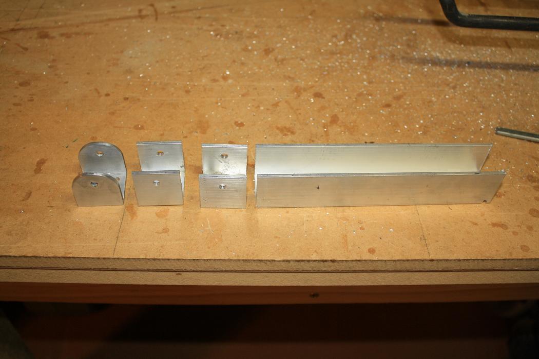
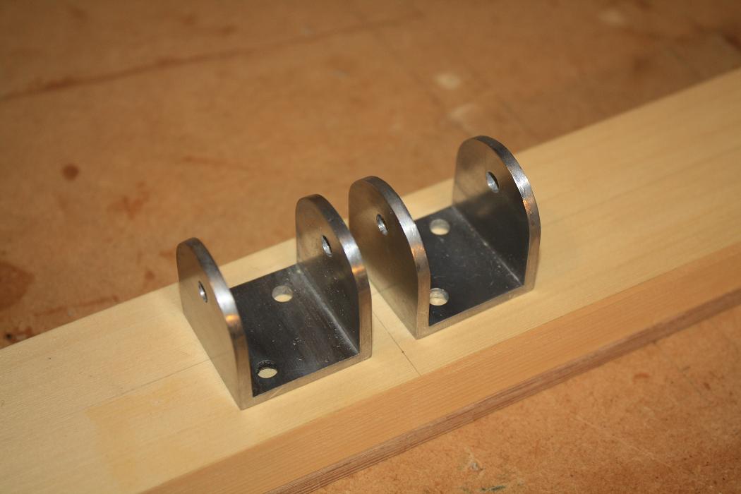
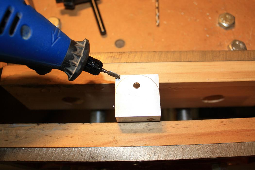 To shape the hinges I used a Dremmel tool to roughly shape the channel to the right shape.
| ||||||
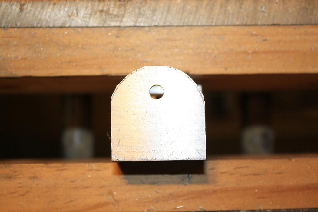 This is what the hinge looks like after rough shaping.
| ||||||
 I then used files and emery tape to smooth the hinges down to the final shape and surface finish. Here is the finished
result. Note that I will not be anodising my hinges like the KR supplied ones as there appears to be some debate as to
the benefits or otherwise of anodising so I will just be giving them a coat of zinc cromate or similar instead.
I then used files and emery tape to smooth the hinges down to the final shape and surface finish. Here is the finished
result. Note that I will not be anodising my hinges like the KR supplied ones as there appears to be some debate as to
the benefits or otherwise of anodising so I will just be giving them a coat of zinc cromate or similar instead.
| ||||||
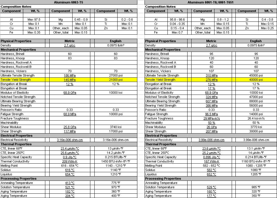 As I said earlier I have since found out that 6063-T5 Aluminium has an inferior shear strength than 6061-T6 and as such
I will not be using the hinges I have made either. I have been trying to source 6061-T6 here in NZ but there does not
appear to be a local supplier so I will need to import this from the US. I have also secured the help of a machinist friend
to manufacture the hinges I require on a CNC mill so I won't be making them by hand either. As you can imagine it
has been a very frustrating exercise to switch to using the correct hinges and I am somewhat unhappy with where things are
at. However that said I will continue to battle on and get the hinges made. The image at right shows the spec sheets for
6063-T5 versus 6061-T6.
As I said earlier I have since found out that 6063-T5 Aluminium has an inferior shear strength than 6061-T6 and as such
I will not be using the hinges I have made either. I have been trying to source 6061-T6 here in NZ but there does not
appear to be a local supplier so I will need to import this from the US. I have also secured the help of a machinist friend
to manufacture the hinges I require on a CNC mill so I won't be making them by hand either. As you can imagine it
has been a very frustrating exercise to switch to using the correct hinges and I am somewhat unhappy with where things are
at. However that said I will continue to battle on and get the hinges made. The image at right shows the spec sheets for
6063-T5 versus 6061-T6.
| ||||||
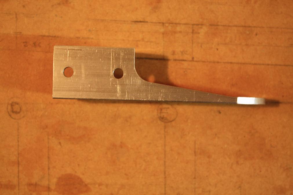
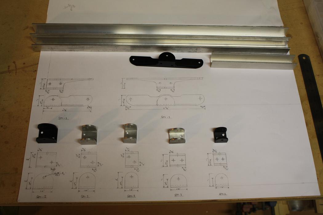 04 Oct 2010 - 07 Oct 2010. It has been a long while since I have been out in the shed. Nice to get back to work. I spent
this week drawing up the hinge components I am getting made for my HS. I will give these to a friend to machine the
parts from two lengths of Aluminum channel I ordered and received from Wicks in September. This is the drawing and the
pieces I used as examples. After looking closely at how the HS actuator arm on Mark Langfords KR works I noted that
unlike the plans his actuator only extends above the centre spar where it connects via a control rod to the bellcrank
forward of the rudder post in the fuselage. As such the HS actuator I have drawn used the rudder actuator arm as the
template but only extends to one side of the HS.
04 Oct 2010 - 07 Oct 2010. It has been a long while since I have been out in the shed. Nice to get back to work. I spent
this week drawing up the hinge components I am getting made for my HS. I will give these to a friend to machine the
parts from two lengths of Aluminum channel I ordered and received from Wicks in September. This is the drawing and the
pieces I used as examples. After looking closely at how the HS actuator arm on Mark Langfords KR works I noted that
unlike the plans his actuator only extends above the centre spar where it connects via a control rod to the bellcrank
forward of the rudder post in the fuselage. As such the HS actuator I have drawn used the rudder actuator arm as the
template but only extends to one side of the HS.
| ||||||
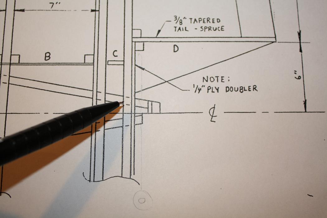 With the drawing finished I got back to the HS itself. I note from the plans that a 1/4" Ply Doubler is required on the back
of the rear spar between the two inner HS templates. You can see the doubler in the picture.
With the drawing finished I got back to the HS itself. I note from the plans that a 1/4" Ply Doubler is required on the back
of the rear spar between the two inner HS templates. You can see the doubler in the picture.
| ||||||
 I cut out a piece of 6mm ply to use as the doubler, however after cutting it to length and roughly to shape I wasn't happy
with the result so have decided to remake it.
I cut out a piece of 6mm ply to use as the doubler, however after cutting it to length and roughly to shape I wasn't happy
with the result so have decided to remake it.12 Oct 2010. I cut out a new doubler and this time used the bench saw to cut the edges to the correct angle. The finished piece now fits well. It will need a little filing to blend it with the spar but I will do this after it is glued in place. | ||||||
 I then set up for and glued the doubler into place on the rear spar
| ||||||
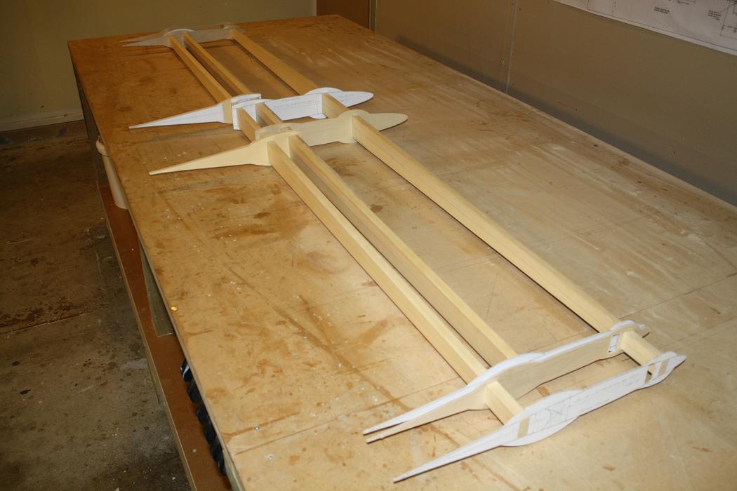
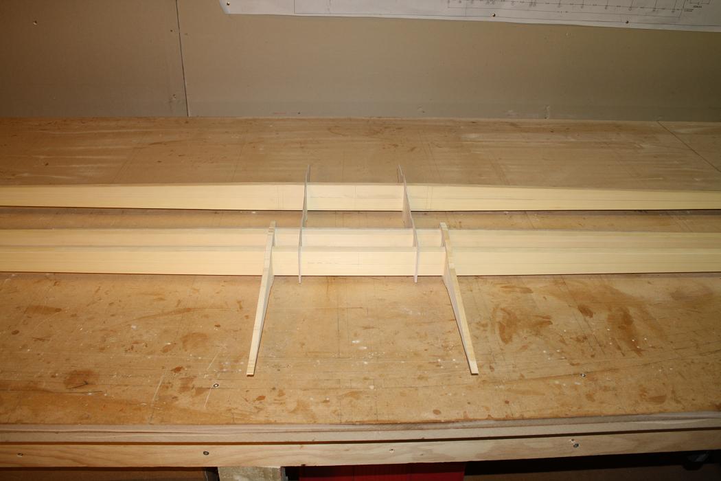
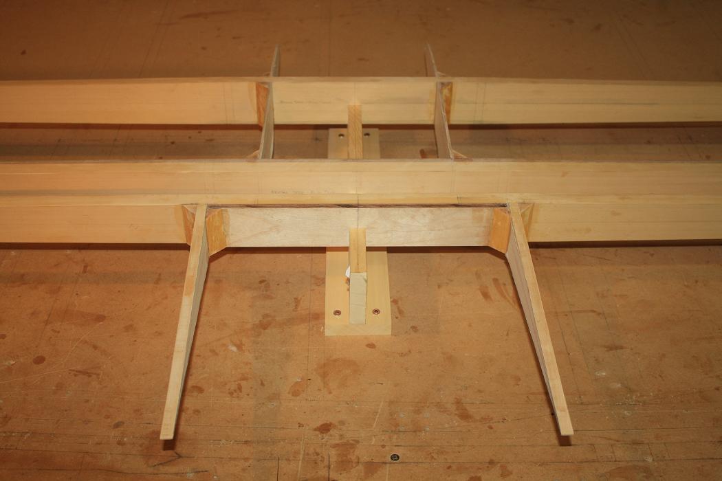
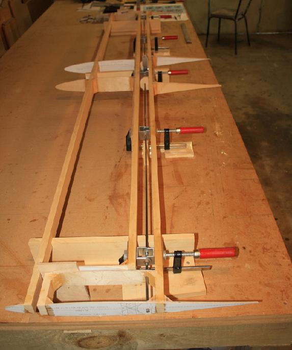
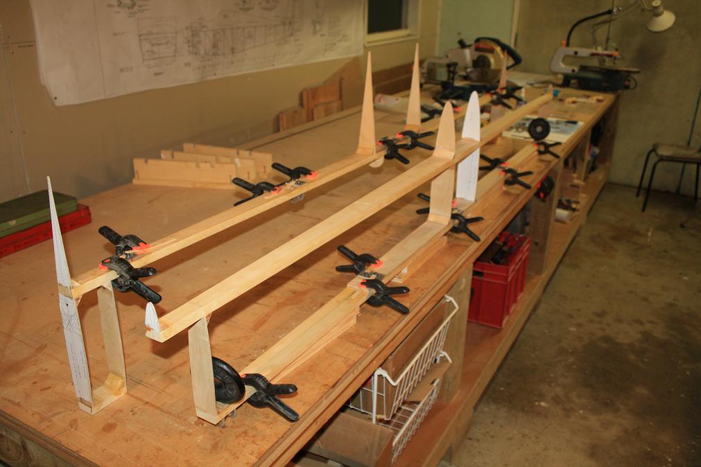
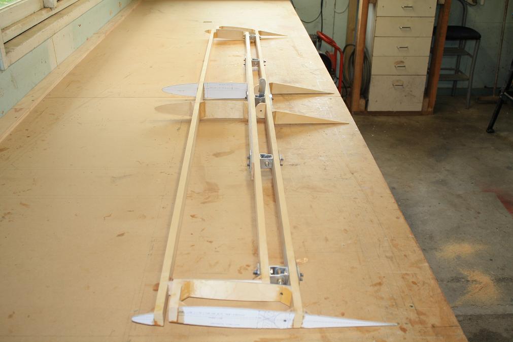
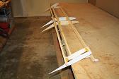
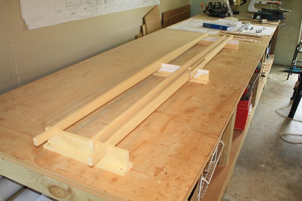 13 Oct 2010. Tonight I started making a jig to mount the HS spars in while they are being glued. I have decided to
do this after reading Mark Langford's site and noting that he made sure his HS was perfectly square and level before gluing.
The picture at right shows the finished jig with the spars inserted after it was completed the next day.
13 Oct 2010. Tonight I started making a jig to mount the HS spars in while they are being glued. I have decided to
do this after reading Mark Langford's site and noting that he made sure his HS was perfectly square and level before gluing.
The picture at right shows the finished jig with the spars inserted after it was completed the next day.
| ||||||
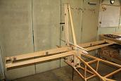
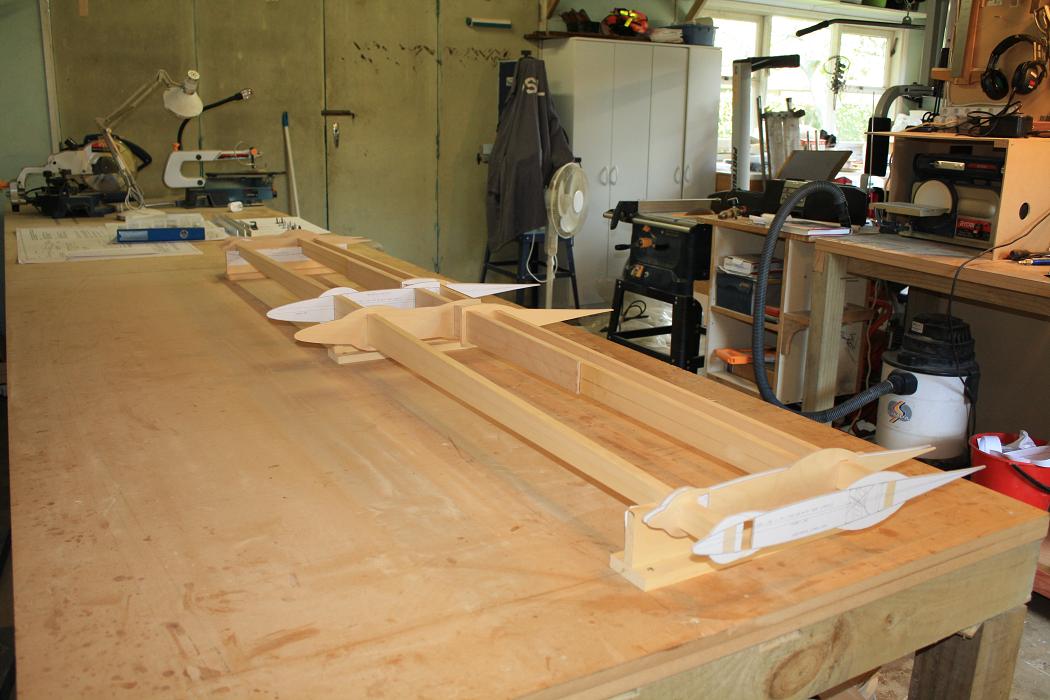 14 Oct 2010. After setting up the jig and fitting the spars I then attached the rib templates.
| ||||||
 Then cut and fit the leading edge sub spars to the balance horns.
| ||||||
 And lastly spent a couple of hours preparing the gussets for the inner HS ribs and glueing these into place.
| ||||||
 15 Oct 2010. Out again to the shed this evening and I removed the clamps from the yesterdays glueing. Then spent a couple of
hours removing the 'wings' from the ribs and carefully shaping the ribs down to match the spars. Very happy with the result.
15 Oct 2010. Out again to the shed this evening and I removed the clamps from the yesterdays glueing. Then spent a couple of
hours removing the 'wings' from the ribs and carefully shaping the ribs down to match the spars. Very happy with the result.
| ||||||
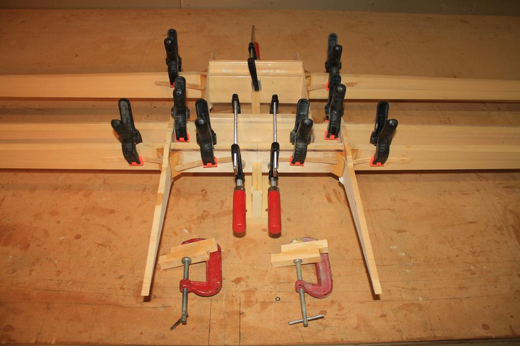
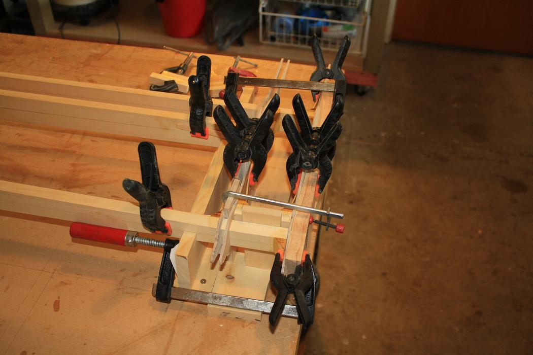
 Sun 17 Oct 2010. Today I spent the day cutting, fitting and glueing the gussets for the port and startboard balance horns.
This is the starboard balance horn with the clamps fitted and the photo taken from the rear of the HS to show the clamp
arrangement.
Sun 17 Oct 2010. Today I spent the day cutting, fitting and glueing the gussets for the port and startboard balance horns.
This is the starboard balance horn with the clamps fitted and the photo taken from the rear of the HS to show the clamp
arrangement.
| ||||||
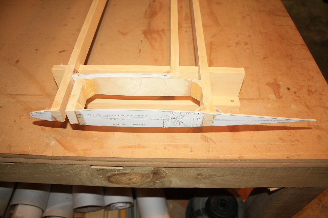
 And this is the port balance horn with the photo taken from the front of the HS. I have to say that having the HS sitting in
jigs has made putting together the balance horns a lot simpler than the way I did it on the first version of the HS.
And this is the port balance horn with the photo taken from the front of the HS. I have to say that having the HS sitting in
jigs has made putting together the balance horns a lot simpler than the way I did it on the first version of the HS.
| ||||||
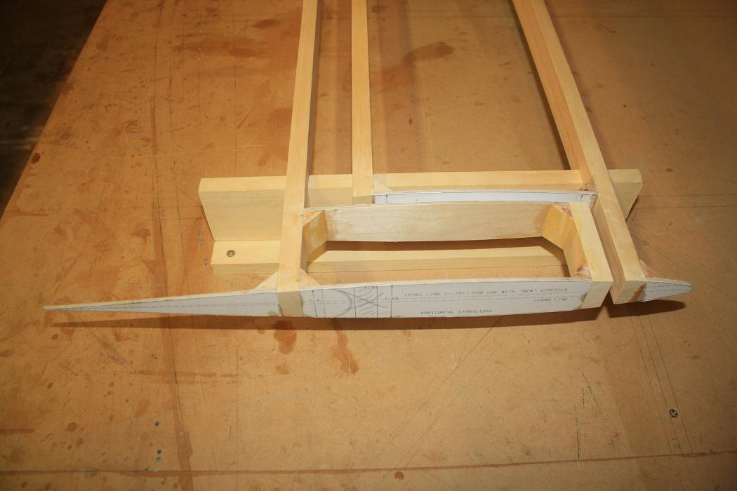
 Mon 18th - Tue 19th Oct 2010. Over the last two days I have trimmed the 'wings' from the balance horn rib templates.
I mostly used a Dremmel cutting bit to cut away the bulk of the ply and then a Dremmel sanding wheel to sand the templates
down to within a half millimeter or so of the lines then finally finished the edges with a small file and sandpaper. This
is the port balance horn after trimming and sanding.
Mon 18th - Tue 19th Oct 2010. Over the last two days I have trimmed the 'wings' from the balance horn rib templates.
I mostly used a Dremmel cutting bit to cut away the bulk of the ply and then a Dremmel sanding wheel to sand the templates
down to within a half millimeter or so of the lines then finally finished the edges with a small file and sandpaper. This
is the port balance horn after trimming and sanding.
| ||||||
 And this is the starboard balance horn.
| ||||||
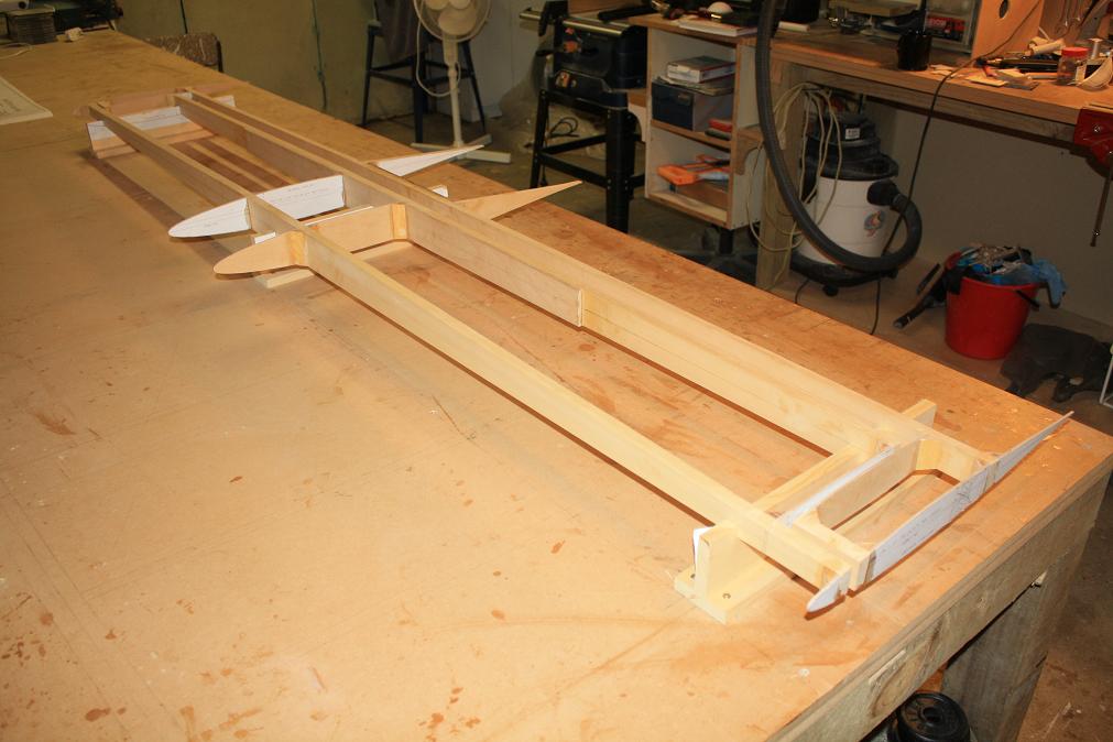 And a photo of the whole HS sitting in the jig.
| ||||||
 Thu 2nd Dec 2010. I picked up my brand new set of KR empennage hinges from Dave Hickman today. Dave has fabricated the hinges
from 6061-T6 channel for me after I gave him the drawings for the hinges. Dave created a CAD file using SolidWorks then loaded
the file into his milling machine and cut the hinges using the machine. The milling machine has made a great job of the hinges.
The photo is of the hinges after I had polished them up.
Thu 2nd Dec 2010. I picked up my brand new set of KR empennage hinges from Dave Hickman today. Dave has fabricated the hinges
from 6061-T6 channel for me after I gave him the drawings for the hinges. Dave created a CAD file using SolidWorks then loaded
the file into his milling machine and cut the hinges using the machine. The milling machine has made a great job of the hinges.
The photo is of the hinges after I had polished them up.
| ||||||
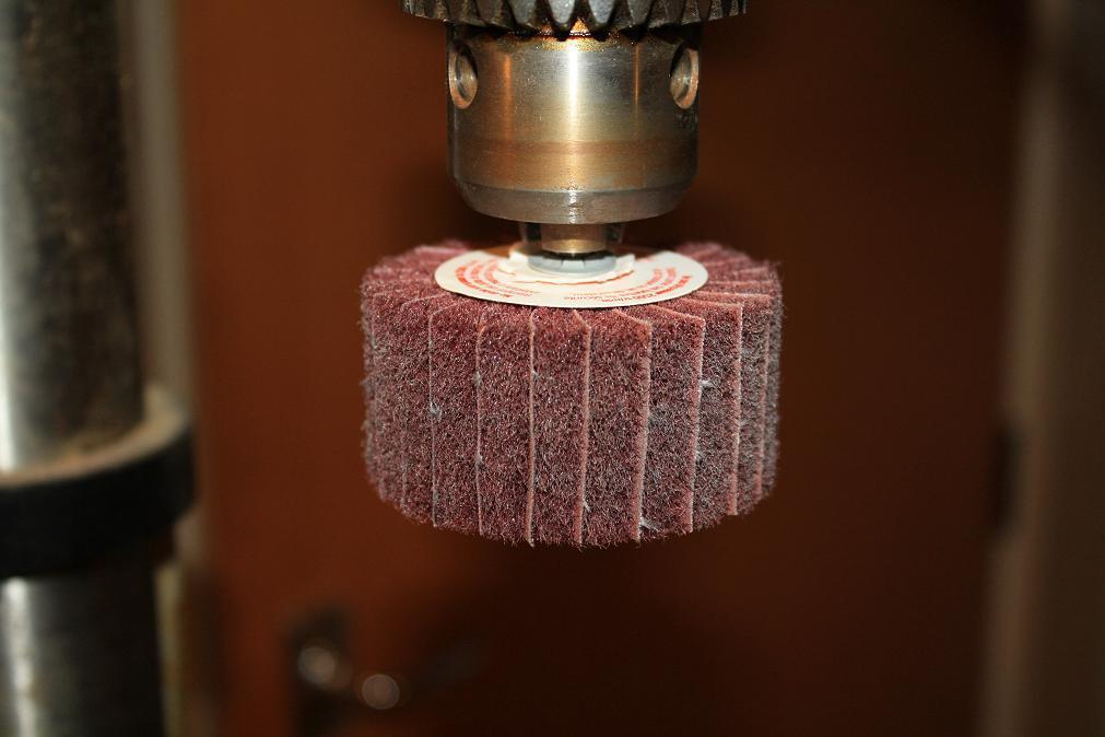 I used a 3M polishing wheel to polish the hinges. I bought it from the local hardware store. It wasn't cheap but it did an
awesome job. Compare the next two before and after photos of what it can achieve.
I used a 3M polishing wheel to polish the hinges. I bought it from the local hardware store. It wasn't cheap but it did an
awesome job. Compare the next two before and after photos of what it can achieve.
| ||||||

| ||||||
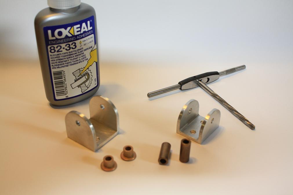 Jan 6th - Jan 12th 2011. Earlier in December I purchased some bronze bushings for the HS and VS hinges. I have spent the last week or
so cutting and filing these bushings to fit the hinges. For each hinge I started with two flanged 5/16" bushings and two plain 5/16"
bushings as well as a 3/16" ream and some Loxeal Loctite to secure the bushings in the hinges.
Jan 6th - Jan 12th 2011. Earlier in December I purchased some bronze bushings for the HS and VS hinges. I have spent the last week or
so cutting and filing these bushings to fit the hinges. For each hinge I started with two flanged 5/16" bushings and two plain 5/16"
bushings as well as a 3/16" ream and some Loxeal Loctite to secure the bushings in the hinges.
| ||||||
 I drilled out the hinge holes to 5/16" then machined the bushings to the correct size and press fit them into the hinges. The outer
hinges have the flanged bushing while the inner hinges have unflanged and there is a plain length of bushing that sits between the
inner hinges to prevent them working the way out of the inner hinge. Note that I did not have ready access to a lathe
to turn the bushings so I used my drill press and hand files to cut them down to the correct size.
I drilled out the hinge holes to 5/16" then machined the bushings to the correct size and press fit them into the hinges. The outer
hinges have the flanged bushing while the inner hinges have unflanged and there is a plain length of bushing that sits between the
inner hinges to prevent them working the way out of the inner hinge. Note that I did not have ready access to a lathe
to turn the bushings so I used my drill press and hand files to cut them down to the correct size.
| ||||||
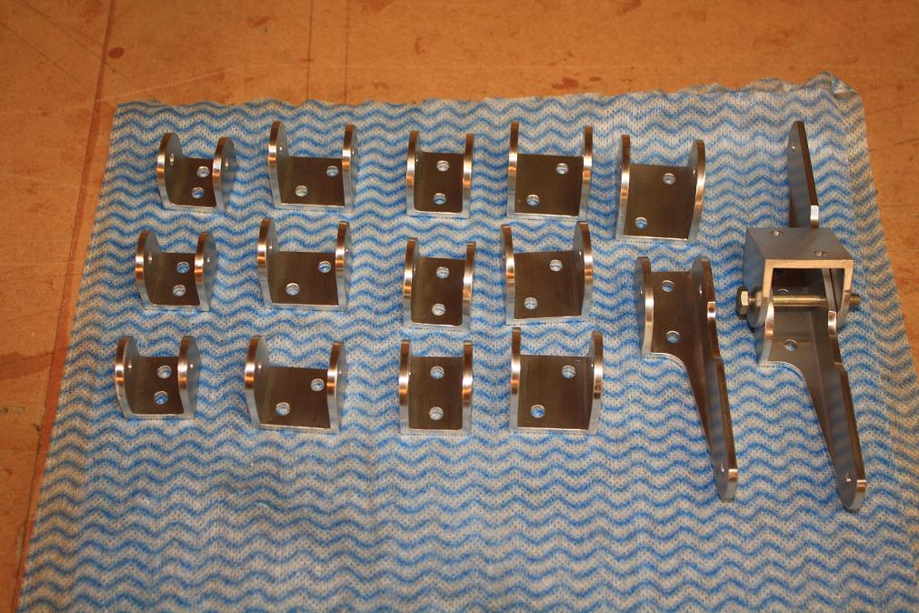
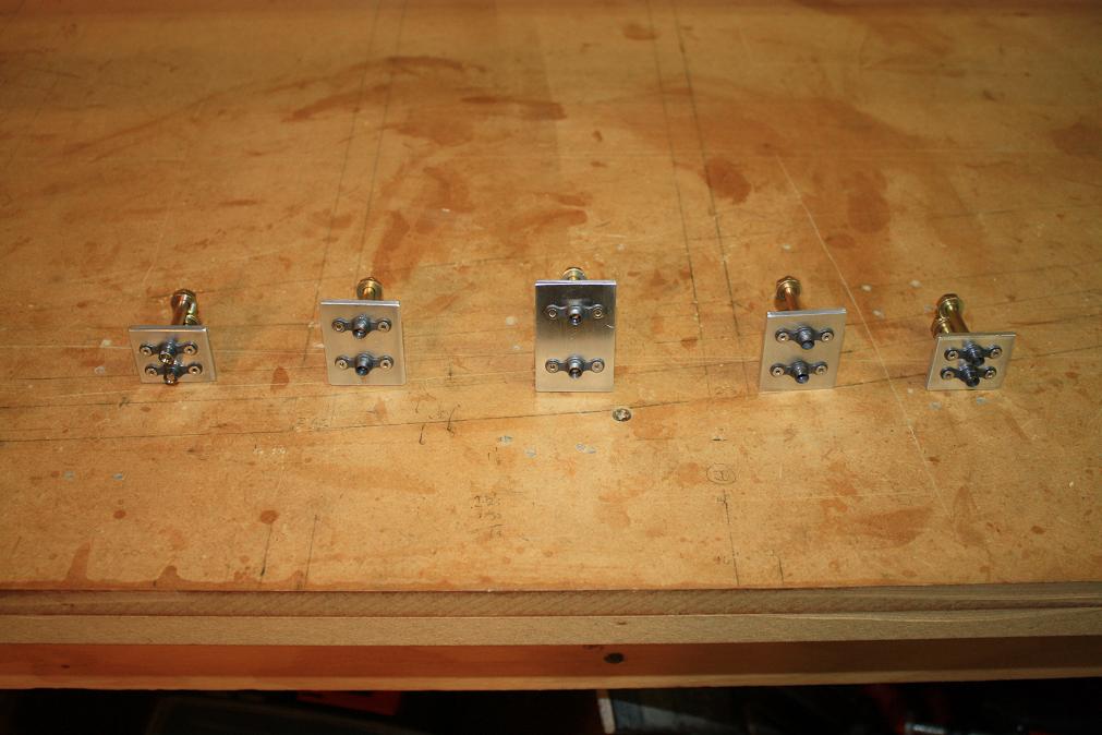
 This is the complete set of hinge hardware for both the VS and HS. As you can imagine it took quite a while to finish off all the
machining.
This is the complete set of hinge hardware for both the VS and HS. As you can imagine it took quite a while to finish off all the
machining.
| ||||||
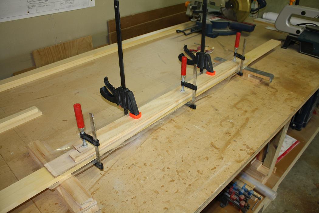
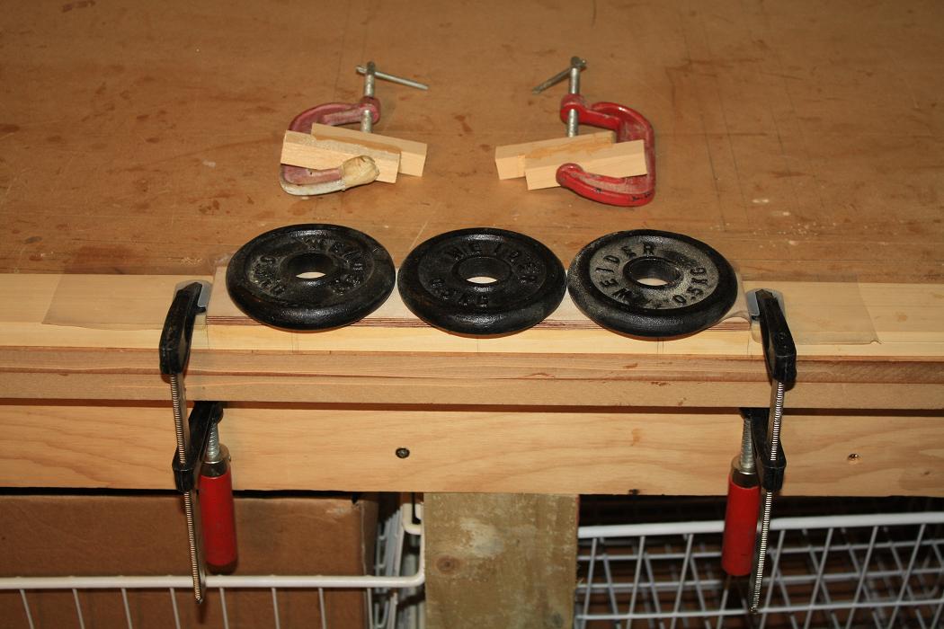
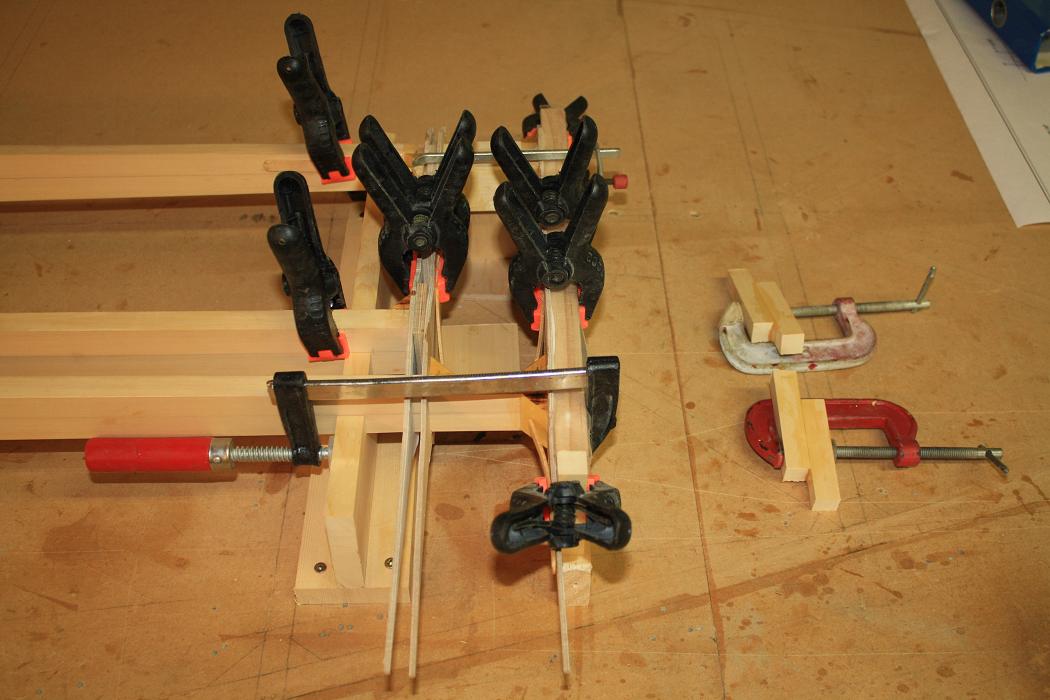
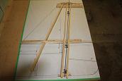
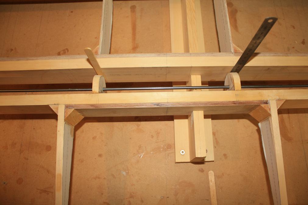 17th - 19th Jan 2011. Over the last couple of evenings I made and then glued into place the spacers that fit between the center
and rear spars of the HS. To align the spacers while the glue dried I have purchased a length of 3/16" steel rod which runs the entire
length of the HS. This photo shows the spacers in place with the aligning rod holding them and a couple of wedges to hold the spacers
in place. Note that the aligning rod is resting on the jigs which have been cut to accept the rods as well.
17th - 19th Jan 2011. Over the last couple of evenings I made and then glued into place the spacers that fit between the center
and rear spars of the HS. To align the spacers while the glue dried I have purchased a length of 3/16" steel rod which runs the entire
length of the HS. This photo shows the spacers in place with the aligning rod holding them and a couple of wedges to hold the spacers
in place. Note that the aligning rod is resting on the jigs which have been cut to accept the rods as well.
| ||||||
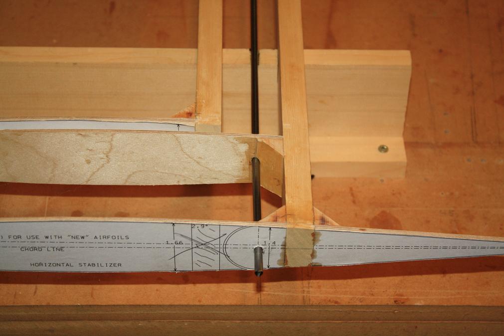 Another shot of the rod and how I inserted it right through all the hinge points. Note that the holes in the balance horn will be
filled in later.
Another shot of the rod and how I inserted it right through all the hinge points. Note that the holes in the balance horn will be
filled in later.
| ||||||
 Once the spacers were glued I then sanded them to ensure the elevator could move through the full range of travel required.
| ||||||
 30 degrees up and 20 degrees down.
| ||||||
 20th - 22th Jan 2011. Next up is the 2.5mm ply backing plates for the hinges on the spars. I fabricated these over the last couple
of days.
20th - 22th Jan 2011. Next up is the 2.5mm ply backing plates for the hinges on the spars. I fabricated these over the last couple
of days.
| ||||||
 And glued them into place in one hit along with the hinges.
| ||||||
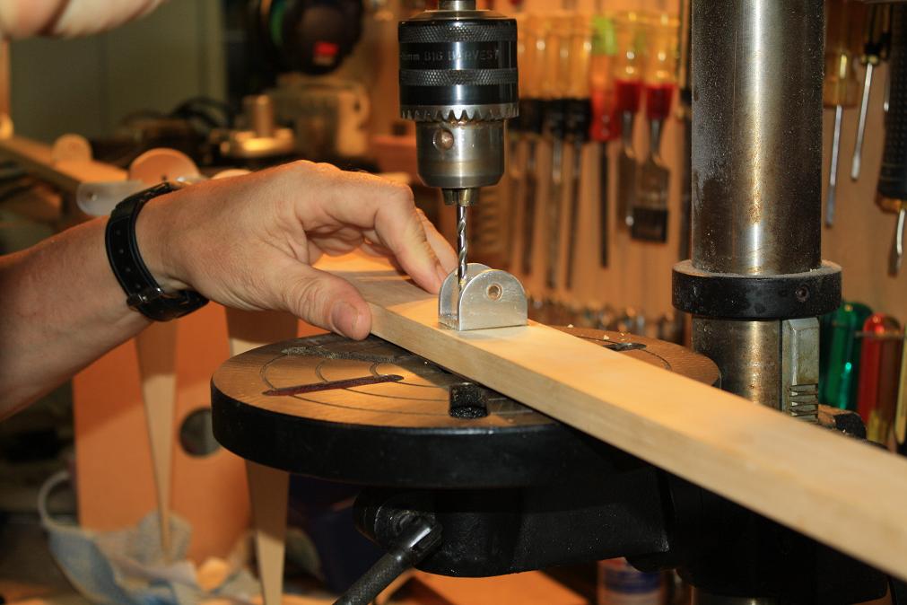 23rd Jan - 3rd Feb 2011. With the backing plates in place I moved on to the nutplates for the bolts. To start with I drilled the
holes for the bolts through the spars. The hinges are already glued in place and aligned so it was a relatively simple matter to
get the spars level and drill through the existing hinge holes.
23rd Jan - 3rd Feb 2011. With the backing plates in place I moved on to the nutplates for the bolts. To start with I drilled the
holes for the bolts through the spars. The hinges are already glued in place and aligned so it was a relatively simple matter to
get the spars level and drill through the existing hinge holes.
| ||||||
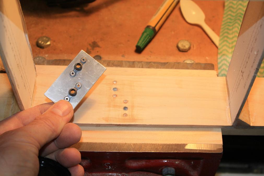
 The nutplates themselves are relatively easy to make. After cutting the 1/8" 6061-T6 to the dimensions I need I then clamp them
over the holes through the spars and use a home made center punch made from a piece of 3/16" rod to mark the position of where I need
to drill the holes. I didn't want to run a drill through the spar holes a second time as this would risk elongating the holes if the
drill alignment was slightly wrong. This method worked mostly ok but I had to remake a couple of the backing plates after the drill
wandered off the center mark.
The nutplates themselves are relatively easy to make. After cutting the 1/8" 6061-T6 to the dimensions I need I then clamp them
over the holes through the spars and use a home made center punch made from a piece of 3/16" rod to mark the position of where I need
to drill the holes. I didn't want to run a drill through the spar holes a second time as this would risk elongating the holes if the
drill alignment was slightly wrong. This method worked mostly ok but I had to remake a couple of the backing plates after the drill
wandered off the center mark.
| ||||||
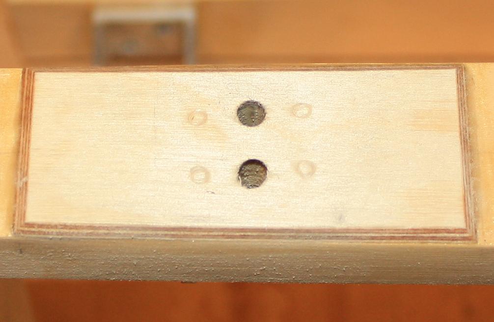 Actually glueing the nutplates to the spars required marking the ply backing plates where the anchor nuts rivets protrude from the
back of the nutplates and then drilling a small indentation at each point to allow the nutplate to sit flush against the ply.
Although not super clear, in this picture you can see the marks made by the rivets of one of the nutplates after I pressed the nutplate
against the ply.
Actually glueing the nutplates to the spars required marking the ply backing plates where the anchor nuts rivets protrude from the
back of the nutplates and then drilling a small indentation at each point to allow the nutplate to sit flush against the ply.
Although not super clear, in this picture you can see the marks made by the rivets of one of the nutplates after I pressed the nutplate
against the ply.
| ||||||
 After marking and drilling all the indentations and making sure the nutplates were sitting flush, I glued them all at the
same time. Note that the hinge bolts were screwed into the nutplates but not tightly. They were just in place to ensure the
plates were aligned correctly and to ensure glue didn't get into the bolt holes. If I had torqued up the bolts it is likely the pressure
would have squeezed all the glue from the back of the plates and the joint would not have been solid. As such I just used the tried and
true method of clamping with popsicle sticks.
After marking and drilling all the indentations and making sure the nutplates were sitting flush, I glued them all at the
same time. Note that the hinge bolts were screwed into the nutplates but not tightly. They were just in place to ensure the
plates were aligned correctly and to ensure glue didn't get into the bolt holes. If I had torqued up the bolts it is likely the pressure
would have squeezed all the glue from the back of the plates and the joint would not have been solid. As such I just used the tried and
true method of clamping with popsicle sticks.
| ||||||
 With the nutplates glued and the clamps removed, I assembled the HS and torqued the bolts to 24 inch/pounds as
required for AN-3 bolts and as listed in the table on the KR2 plans. (Note that I have purchased a specialist
torque wrench which measures in the range 10-180 inch/pounds for this purpose.)
With the nutplates glued and the clamps removed, I assembled the HS and torqued the bolts to 24 inch/pounds as
required for AN-3 bolts and as listed in the table on the KR2 plans. (Note that I have purchased a specialist
torque wrench which measures in the range 10-180 inch/pounds for this purpose.)
| ||||||
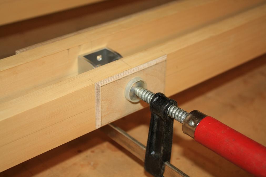
 13th May 2011. With the HS complete I have been working on building the HS and VS mounts in the rear fuselage. While measuring up for the rear 'O'
position web I realised that I had incorrectly attached the nutplate for the centre line hinge to the middle spar. The nutplate actually needs to
be attached to the spar support web. As such I needed to remove the nutplate which I did this evening. This took a little while to accomplish using
a file to remove the glue along the side of the nutplate and then a chisel to pop the plate off the spar. I have since found out that a heat gun
can be used to soften the resin glue to make it easier to remove. Fortunately I managed to get it off without damaging the HS spar.
13th May 2011. With the HS complete I have been working on building the HS and VS mounts in the rear fuselage. While measuring up for the rear 'O'
position web I realised that I had incorrectly attached the nutplate for the centre line hinge to the middle spar. The nutplate actually needs to
be attached to the spar support web. As such I needed to remove the nutplate which I did this evening. This took a little while to accomplish using
a file to remove the glue along the side of the nutplate and then a chisel to pop the plate off the spar. I have since found out that a heat gun
can be used to soften the resin glue to make it easier to remove. Fortunately I managed to get it off without damaging the HS spar.
| ||||||
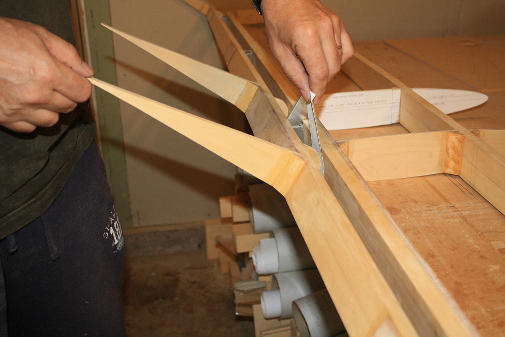
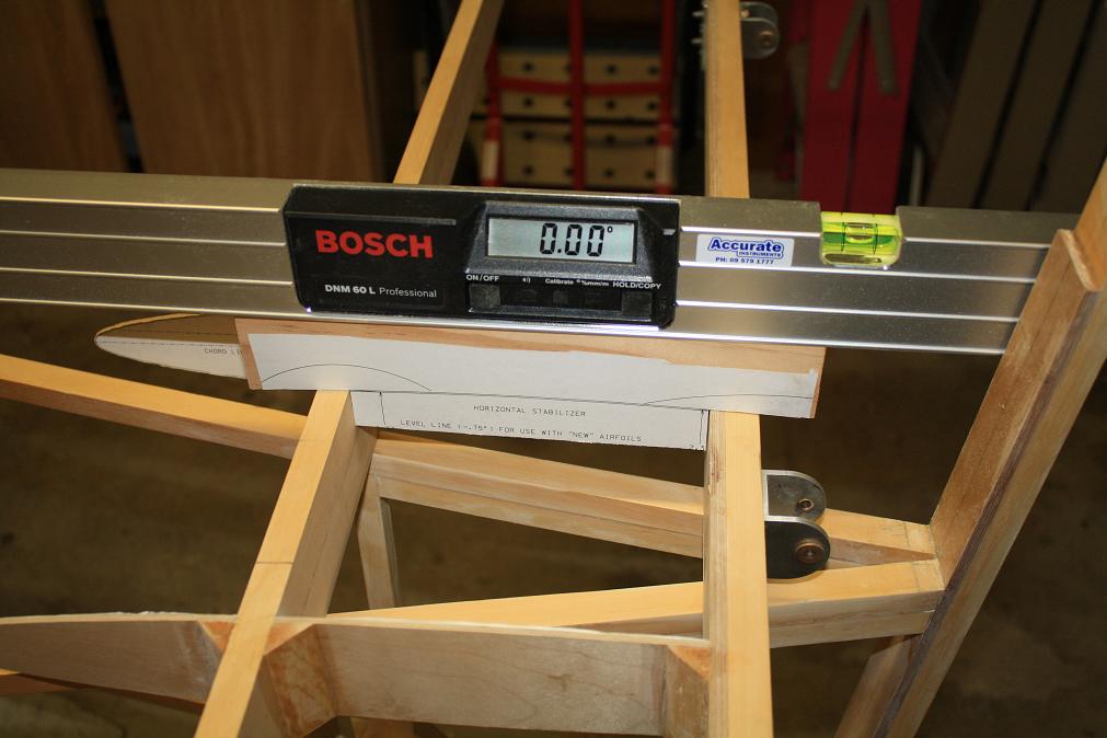 With the nutplate removed I then mounted the HS on the fuselage and used my digital level and a jig I have made to get the HS at the correct angle
of attack relative to the fuselage.
With the nutplate removed I then mounted the HS on the fuselage and used my digital level and a jig I have made to get the HS at the correct angle
of attack relative to the fuselage.
| ||||||
 To level the HS I have made a small fillet of timber to sit under the centre spar. This lifts the center spar to get the HS to sit with the -0.75 degree
chord line level. (Note that I will need to remove the timber from the fillet outside of the fuselage sides as it will alter the underside profile of
the HS.)
To level the HS I have made a small fillet of timber to sit under the centre spar. This lifts the center spar to get the HS to sit with the -0.75 degree
chord line level. (Note that I will need to remove the timber from the fillet outside of the fuselage sides as it will alter the underside profile of
the HS.)
| ||||||
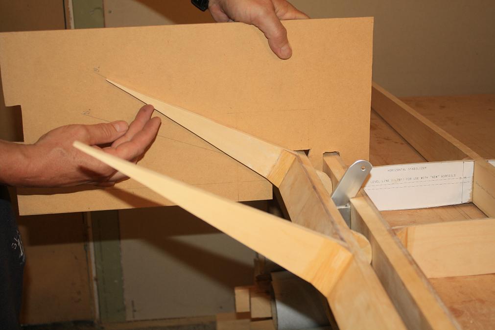
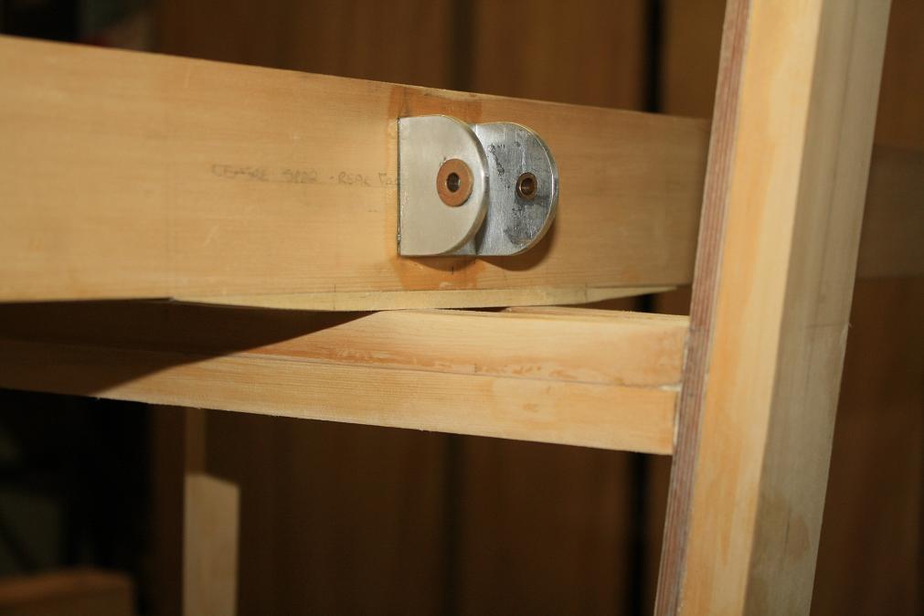
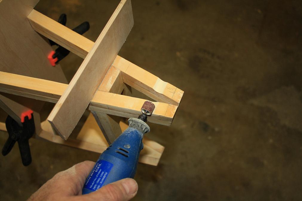 With the HS correctly leveled I then needed to make an indentation in the top longerons to enable the HS to move to its full 20 degree downward deflecton.
I used my dremmel tool to make the initial cut.
With the HS correctly leveled I then needed to make an indentation in the top longerons to enable the HS to move to its full 20 degree downward deflecton.
I used my dremmel tool to make the initial cut.
| ||||||
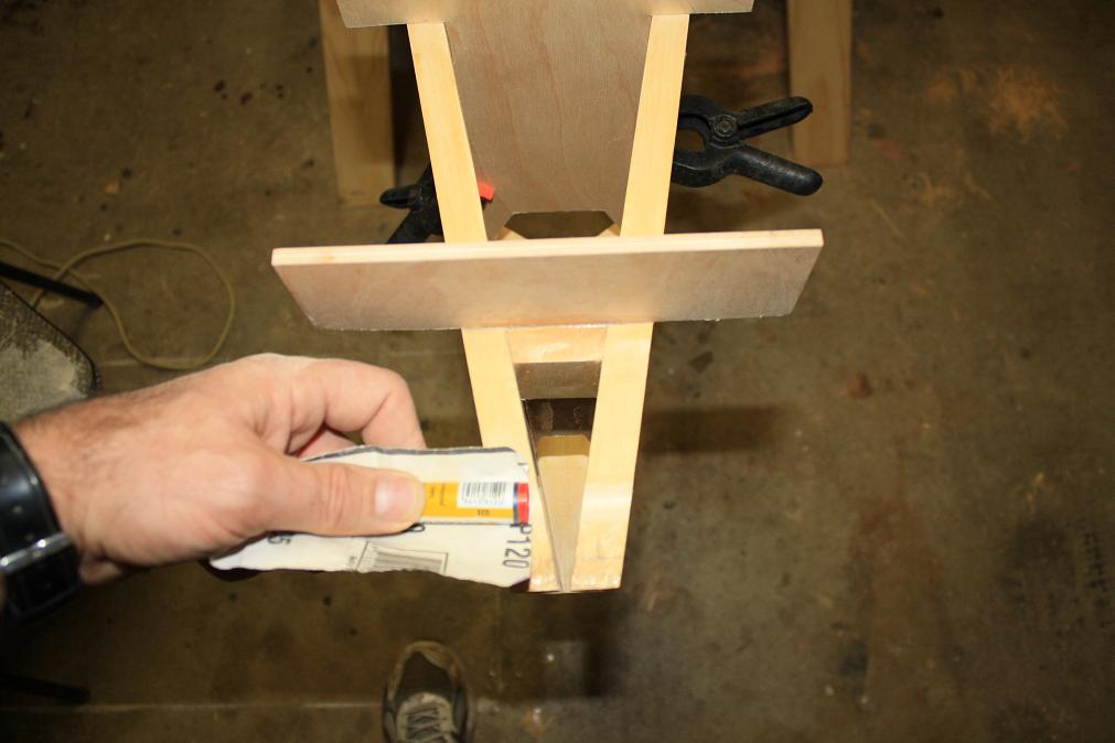 And then finished off with some 120 grit sand paper wrapped around a vivid marker.
| ||||||
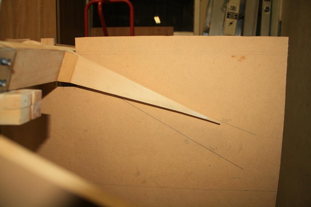 And this is the resultant test for the deflection. I will probably need to recheck this at a later time but for the time being it will suffice.
| ||||||
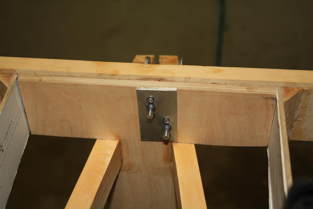 July 3rd 2011. Today I drilled the holes through the rear HS spar and the rear support web to secure the HS to the fuselage.
| ||||||

www.kiwikr.co.nz